Contents
Scalable IEEE 1394 (FireWire)-Based Motion Controller
Introduction
 Research on the JHU Snake Robot seeks to improve minimally invasive surgery (MIS) of the throat and upper airways by providing surgeons with dexterous robotically-controlled tools. This dexterity is achieved by incorporating more degrees of freedom (dof). However, research on different types of multi-axis surgical robots is often mired in the hardware construction effort.
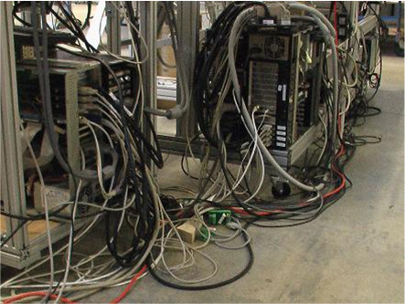
This project originates in part from the need to improve upon the old multi-axis controller of the Snake and extend it other projects. The original design uses a centralized I/O arrangement, whereby signals are transmitted in raw analog form over long cable bundles running between the robot and the computer. Though a straightforward method, the cumbersome wiring involved introduces a wide range of practical difficulties, as captured in Figure 1.
We have developed a real-time control system that capitalizes on a high speed serial network (IEEE 1394), low-latency FPGAs, and advancing computing power. Our goal is to provide an abstract interface and scalable mechanisms for highly configurable, fine-grain, real-time control to help simplify the development of dexterous surgical robots from both hardware and software perspectives. Particularly in education and research, this would facilitate the exploration of complex systems by allowing for more dexterity, reliability, and scalability.
Centralized Processing, Distributed I/O Architecture
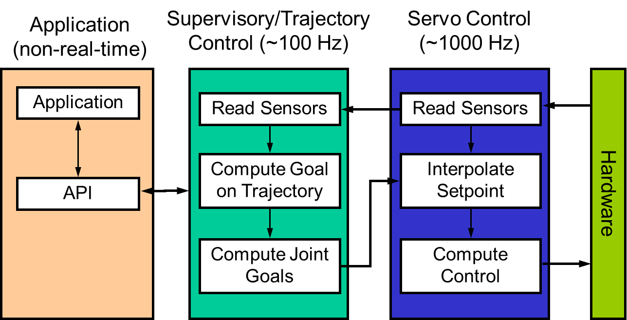 Robot systems are concurrent by nature: multiple joints must be controlled simultaneously, and there is often a hierarchy of control strategies. A typical robot controller (Figure 2) contains “loops” for servo control, supervisory (e.g., trajectory) control, and the application.
Centralized processing and I/O: In the early days of robotics, controllers consisted of a central computer with a rack of joint-level control boards on a parallel bus, such as ISA, Q-Bus, Multibus, or VME; this was necessary for performance reasons, as computers and networks were slow. The disadvantage of this approach is that the cabling between the computer and the robot can grow to unwieldy proportions.
Distributed processing and I/O: The emergence of high-speed serial networks, such as CAN, Ethernet, USB, and IEEE 1394, made it possible to physically distribute the joint-level control boards. By placing these components inside the robot arm or base, thick cables containing wires for commands and feedback could be replaced by a thin network cable. Here the drawback is that the discrete control boards make the software development environment more complex.
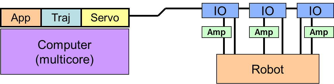
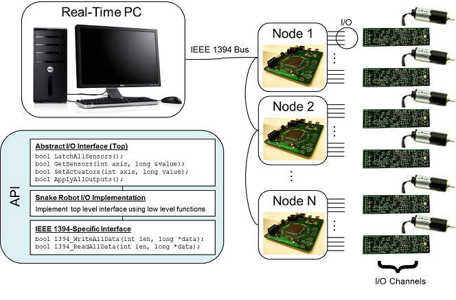
Centralized processing, distributed I/O: Given the advances in processor performance and architecture, coupled with the high data rates of modern serial networks, we advocate a centralized processing, distributed I/O approach (Figure 3). This can be achieved by utilizing FPGAs to provide direct, low-latency interfaces between the network and the hardware. This preserves the reduction in cabling while allowing all software to be implemented on a single real-time computer, freeing developers from having to learn the idiosyncrasies of various embedded microprocessors.
We chose IEEE 1394 as the high speed network because it offers ample bandwidth (400 Mbps for 1394a), low latency, and the ability to daisy chain nodes. We note, however, that it is not necessarily the single best choice given the alternatives and emerging technologies.
System Description
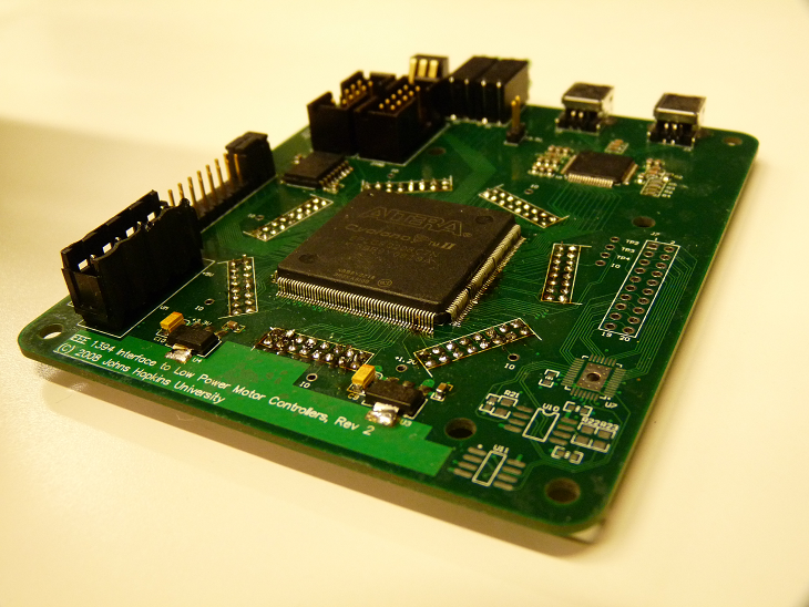
Figure 4 provides an overview of the control system. The controller is shown in Figure 5 installed on the Snake Robot.
Electronics Design
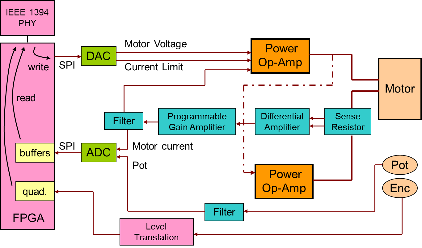
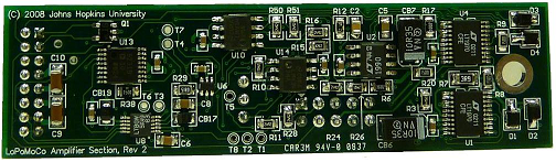
Amplifier Section: Also referred to as an I/O channel, this section contains the power amplification and I/O required to control one dc motor. I/O signals include a motor enable line as well as an op amp fault line to indicate overheating. Other components include an ADC, a DAC, and a digital potentiometer. The dual-channel ADC digitizes analog feedback, namely potentiometer voltages and motor currents. The DAC provides motor speed and current limit commands. The board outputs incremental encoder pulses that are decoded by the FPGA to compute relative displacement and velocity.
The motor current feedback gain and operation mode (speed or torque control) can be programmed through the digital pot. This flexibility allows for adaptation of the board to robots with different low-power motors.
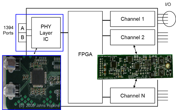
 Digital Section: The digital section (or node) accesses the I/O channels and handles bus transactions. Its core components are an FPGA and a two-port IEEE 1394a physical layer chip. IEEE 1394 allows up to 63 nodes per bus; the maximum number of channels one node can accommodate is governed largely by its resident FPGA, but typical low cost models are powerful enough for this application.
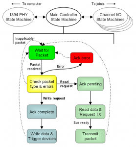
Firmware Section: Most of the functionality of each node is implemented as firmware on the FPGA. The state machine in Figure 6 describes the top level operation. Action is initiated when the computer requests a data transaction, for instance a sensor read or an actuator write. The FPGA on the addressed node responds immediately with an acknowledgment. For reads, the FPGA sends the requested to the computer with a timestamp. For writes, it triggers the appropriate I/O devices.
I/O operations for all channels, such as encoder counting and SPI, run in parallel as separate submodules and are accessed by the higher level part of the firmware that also manages bus transactions.
 Application Programming Interface

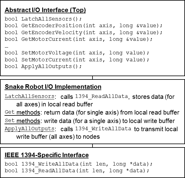 We developed an application programming interface (API) for the above control system. The interface has the three-layer hierarchy shown in Figure 7. The top layer consists of abstract I/O operations that can be used for different robots. It includes commands to latch all sensors and to apply all outputs. Read and write operations access one axis at a time.
The next layer down implements the abstract interface for a particular robot. Because software-induced latency (about 35 µs per transaction) is a key concern, the middle API layer for the Snake is customized to bundle data for all axes of a node into a single bus transaction. This layer provides access to individual axes via local buffers that are filled by LatchAllSensors and emptied by ApplyAllOutputs.
Finally, the bottom layer contains function calls to the IEEE 1394 API library (libraw1394).
Software for the Snake is based on the cisst libraries, which contain resources that ease the development of robotic systems. The API is being integrated into the cisst libraries.
Use Case: The Snake Robot
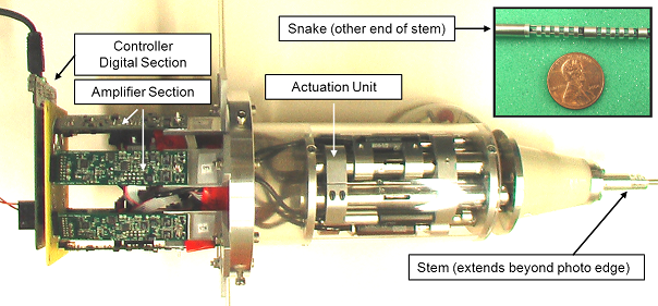
 A unique design targeted for MIS of the upper airways, the Snake Robot features a teleoperated dexterous end effector that appears at the distal end of a narrow (4 mm), meter-long stem through which the actuation wires run; the actuation unit (AU) is located at the proximal end of the stem.
The end effector, or snake-like unit (SLU, Figure 8), is constructed using four superelastic NiTi backbones. The central primary backbone is surrounded by three parallel secondary backbones at equally-spaced radial distances and angles. All four backbones are fixed to the distal end disc, while only the primary backbone is fixed to the proximal base disc. The secondary backbones are free to glide through holes in the intermediate spacer discs.
Two degrees of freedom result from pushing and pulling the secondary backbones. In the Snake, two 4.2 mm diameter SLUs are connected in series for a total length of about 40 mm, achieving four degrees of freedom via six actuators. Including gripper actuation, the AU contains seven control axes in total.
Experiments and Results
Preliminary performance tests: We ran some initial tests to gauge the attainable speeds and latencies of IEEE 1394 transactions. The measured speeds are more than capable of transferring data for many control axes. For example, 1500 bits, or roughly 15-20 axes, can be accommodated at a cost of 5 µs in each direction. The key figures are the latencies, which are on the order of 35 µs per transaction (read or write). These findings are summarized in the plot below.
 Robot tests: Control software is run on an RTAI-patched Linux PC (2.0 GHz Pentium 4, 512 MB RAM). At the trajectory level, the software accepts six-dof Cartesian configurations and computes the inverse kinematics in 125 Hz cycles. The resulting joint values are transferred to the servo level, which updates the actuator positions at a nominal 1 kHz.
The orientation of the robot end effector can be described in terms of yaw (γ), pitch (β), and roll (α) angles. In our tests we drive the robot with sinusoidal γ and β angles and observe the α angle that results.
α = tan-1 [sin β sin γ / (cos β + cos γ)]
Servo rates: The robot path in response to the test input is plotted in Figure 9 for different servo rates. The servo loop duty cycles (busy periods) are listed in Table 1. Bus transaction latencies prescribe an upper limit on the servo rate. In keeping the duty cycle at a safe margin (roughly 50%), the robot appears to work as intended.
| Servo Rates (One Node) | # of Nodes (At 1 kHz) | |||
|---|---|---|---|---|
| Rate | Duty Cycle | Nodes | Duty Cycle | |
| 800 Hz | 288 µs – 23% | 1 | 298 µs – 30% | |
| 1000 Hz | 298 µs – 30% | 2 | 334 µs – 33% | |
| 1250 Hz | 290 µs – 36% | 3 | 356 µs – 36% | |
| 2000 Hz | 294 µs – 59% | |||
Number of nodes: To determine the scalability of the system, the robot is driven with one, two, and three nodes connected. The extra nodes do not drive mechanical components, but the influence of the extra nodes is retained from an I/O latency standpoint. The resulting paths are plotted in Figure 10. There appears to be no effect from increasing nodes, likely because the extra overhead does not lead to violated timing requirements.
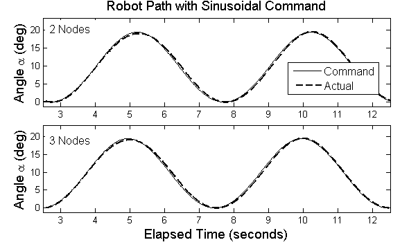 The times listed in Table 1 show that the duty cycle of the servo loop increases with the number of nodes. The computer can write all nodes with a single broadcast packet, so the time increase is due primarily to extra read transactions (the extra computation and transfer times take only a few μs). A rough extrapolation based on an additional 40 μs per node suggests that this system can handle up to six nodes at a 50% duty cycle. This figure may be increased by improving upon the naive implementation of read transactions.
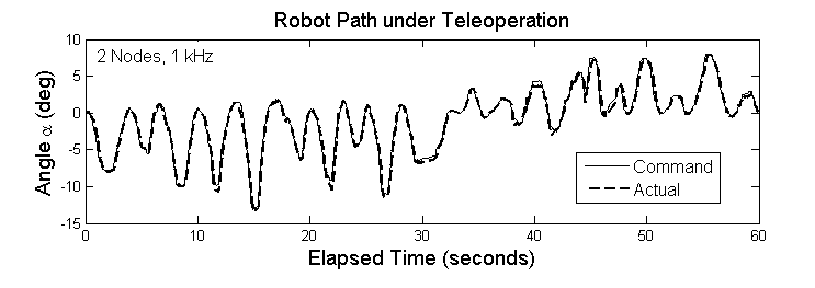
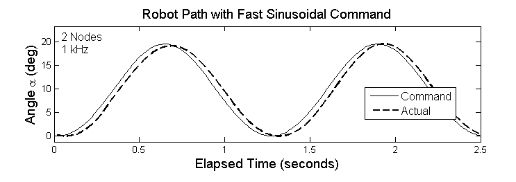
Teleoperation: A teleoperation setup is used to evaluate the performance of the control system under realistic conditions. Position commands from a PHANTOM Omni haptic device are sent over a local area network to the robot computer. Figure 11 shows the path of the robot guided by an Omni. The system appears to work as expected, except where abrupt changes in the path are commanded, likely due to the mechanical limitations of the robot. This type of delay is further illustrated in Figure 12, the result of applying a faster sinusoidal input command. The lag is about 60 ms.
Summary
We developed a scalable robot motor controller that uses IEEE 1394 to link a computer with robot joints; this led to a centralized computation, distributed I/O approach. We discussed the technologies that enable this architecture and outlined its advantages over traditional schemes.
Real-time performance of the controller was demonstrated by application to the JHU Snake Robot, a dexterous multi-axis robot designed for MIS of the throat and upper airways. The controller is capable of real-time control with rates up to several kilohertz; higher rates such as 10 kHz appear to be challenging with the current setup based on the measured latencies.
In the future we aim to implement efficient read transactions for multiple nodes, and make the API compatible with the SAW medical robotics framework. For subsequent developments, please visit Open Source Mechatronics, part of the da Vinci Research Kit.
Project Personnel
-
Graduate Students
-
Paul Thienphrapa
-
Fran Wu
-
-
Faculty
-
Peter Kazanzides
-
Funding
-
NSF ERC #EEC9731748
-
NSF #MRI0722943
-
Internal funds
Affiliated Labs
Publications
Design of a scalable real-time robot controller and application to a dexterous manipulator Proceedings Article
In: IEEE Intl. Conf. on Robotics and Biomimetics (ROBIO), pp. 2295-2300, Phuket, Thailand, 2011.
A scalable system for real-time control of dexterous surgical robots Proceedings Article
In: IEEE Intl. Conf. on Technologies for Practical Robot Applications (TePRA), pp. 16-22, Woburn, MA, 2009.
A Distributed I/O Low-Level Controller for Highly-Dexterous Snake Robots Proceedings Article
In: IEEE Conf. on Biomedical Circuits and Systems (BioCAS), Baltimore, MD, 2008.
Centralized processing and distributed I/O for robot control Proceedings Article
In: IEEE Intl Conf. on Technologies for Practical Robot Applications (TePRA), pp. 84-88, Woburn, MA, 2008.