Contents
Summary
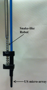
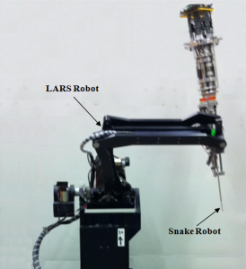
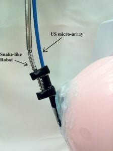
The aim of this project is to control the dexterous snake-like robot under ultrasound imaging guidance for ultrasound elastography. The image guidance is through an ultrasonic micro-array attached at the tip of the snake-like robot. The snake-like unit with the ultrasonic micro-array can be seen in the figure on the left.In the robotic system developed the snake-like unit is attached to the tip of IBM Laparoscopic Assistant for Robotic Surgery (LARS) system which can also be seen in the figure on the right.
The main role of the LARSnake system in this project is to generate precise palpation motions along the imaging plane of the ultrasound array. With an ultrasonic micro-array B-mode images of a tissue can be obtained however,if at hand compressed and uncompressed images of the tissue are present, than one can obtain the elastgraphy images(strain images) of the malignant tissue which is the main purpose of this project.
Background, Specific Aims, and Significance
The system developed will be used for the Natural Orifice Transluminal Endoscopic Surgery (N.O.T.E.S) which is a minimally invasive surgical technique which uses elastgraphy to detect malignant tissues intraoperatively. Nowadays, ultrasound elastography became a priceless imaging modality while it has some weaknesses. The main disadvantage is that they suffer from low contrast when imaging organs from the surface of the body. The other disadvantage is the difficulty to generate very precise palpation motions along the ultrasound image plane which is needed to form the elastography images from the gathered sequential B-mode images.
To perform N.O.T.E.S in real time, the flexibility of the snake-like robotic system is used such that, an ultrasonic micro-array is attached at the tip of a two-segmented snake robot. The system developed is used to detect spherical lesions(representing the tumor inside the tissue) inside a tissue mimicking phantoms which will be detailed in the below sections.
Technical Approach
Position controlled system design
The initial status of the LARS and snake system which could be controlled by a space mouse. The input from the space mouse is a velocity input so the system was operating in velocity control mode however, for precise motion, the position control of the system was needed which was also an inevitable requirement in implementing the palpation motion. The following procedure is followed in carrying out the design of control mode of operation:
-
A GUI Incremental Position Control is designed such that the user can input the incremental positions and the snake tip moves at that amount.
-
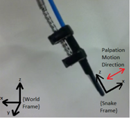
Different coordinate frames are defined such as World CF and Snake Tip CF coordinate frames. The position control can be used in any one of the frames. (In the palpation motion, the position control is implemented always at the snake tip frame since, when the robot is already rotated on one of its axis; the palpation should be at its tip frame which can be seen in the on the left)
Easy to modify GUI design
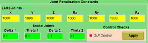
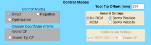
The GUI that has been used so far was for the LARS robot only. A more efficient GUI includes switching from World to Snake tip coordinates easily. In the Control Modes tab above Direct corresponds to direct mapping between 3D mouse and world coordinates, Optimization is for running the constraint optimization algorithm and Palpation mode is for generating periodic maneuvers in the US imaging plane. From the General Settings RCM mode operation and the type of control(position or velocity control) can be set. Since the system to be used is an over-redundant system the joint motion inputs are the outputs of a constraint optimization algorithm [2].To speed things up, an easy to use joint penalization GUI is designed. In this GUI the user can assign arbitrary penalization constants for each joint at real time such that the larger the penalization constant of an actuator, the more difficult that joint moves.
US probe connector manufacturing
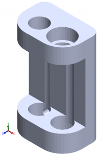
For this purpose, the initial design proposed by Prof. Simaan was used to generate the two piece probe connector. (The initial design can be seen figure on the right, but since the rotation of the US probe around its own axis is not implemented a the tool divided into two to better use the flexibility of snake like units). Manufacturing is done on the rapid prototyping machine.
 Registration between LARS coordinates to US image coordinates
Ideally, a registration could have been performed between the robot coordinate system and the ultrasonic micro-array image coordinate system to determine the direction of the imaging plane along which the palpation motions take place. However, as an alternative to this approach, the perpendicularity of the palpation is established by inspecting the up and down movement of the B-mode images on the Ultrasonix SONIX RP research platform.
Conducting palpation experiments to generate elastography images
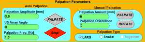
For elastography, two different experiments are conducted. In the experiments a tissue-mimicking breast phantom(CIRS Phantom Model 059) and prostate phantom(CIRS Phantom Model 066) are used. The fist experiment aimed to produce the strain images through a sequence of compressed and uncompressed B-mode images. The motion of the micro-array probe is generated by the snake-like unit on the left. Using the Palpation Parameters GUI on the right, the maneuvers are created at a certain amplitude and at a certain frequency. Using the Manual Palpation part of the GUI the direction of motion is estimated. The second experiment focused on rendering the 3D B-mode image of the prostate. For this purpose, again a sequence of images are gathered, but this time the micro-array probe should be swept the surface of the phantom surface other than the palpation motion. Details of these procedures are present in the experiments section.
System Integration
In the robotic platform developed, a snake-like robot, with two segments, is attached to the tip of a 7 degrees of freedom IBM Laparoscopic Assistant for Robotic Surgery (LARS) system [1]. This integrated kinematically-redundant, 11 degrees of freedom, robotic system is used to generate the palpation maneuvers necessary for gathering compressed and uncompressed RF data frames. The system is capable of achieving the desired palpation motions using different groups of actuator units, such as the first segment, the second segment or a combination of both snake-like segments. The inherent Parallel Linkage Remote-Center-of-Motion (RCM) property of the LARS system makes it suitable for performing N.O.T.E.S in which there is only one entry point, although the workspace for RCM operation is quite limited.
The control of the 11 degrees of freedom robotic platform is established via a constrained optimization algorithm [2]. The constraints used in the algorithm, for the snake component, are the joint position and velocity limits aiming to prevent any damage on the snake backbones. On the LARS side however, the constraints are responsible for making sure that the penetration point stays at its original position with the RCM operation. More specifically, the overall system has three types of motion:
- Coarse Positioning
- Fine Positioning
- Palpation Motion
In coarse positioning, the snake units do not move while the remaining LARS robot dominates the motion which can be considered as the surgeon inserting the probe through a natural orifice. After it is confirmed that the micro-array reaches the target organ or the intracorporeal space, it is aimed to find the malignancies using the snake-like robot in fine positioning mode which can be seen in video on the left. The palpation motion comes into play starting from this phase of the procedure in which the sequential RF data frames are gathered to form the elastography image of the lesion. An example of the palpation motion can be seen in video on the right. In the experiments, the amplitude of the palpation maneuvers was set to 1 mm, but in this video the amplitude is set to 3 mm for better visualization of the motion of the snake-like unit with the ultrasonic micro-array probe.
Video showing palpation motion (on YouTube)
Video showing probe positioning (on YouTube)
The integration of the snake robot with the ultrasound array requires that the array technology be as compact and as flexible as possible to conform to the small size of both the snake robot and the confined surgical fields typical to N.O.T.E.S. The probe designed for this purpose is 3 mm in diameter with a linear array having a total length of 15 mm. The probe consists of 64 elements with a pitch of approximately 0.2 mm. Both the array and the robot stand to benefit from integration so that N.O.T.E.S can be more readily performed using enhanced elasticity images obtained by the optimal palpation motions executed by the snake robot. This initial proof of concept employed an adapter to rigidly connect and support the ultrasound probe to the side of the continuum robot.
Lastly, video below is a simple scenario that illustrates how N.O.T.E.S is performed. In this scenario, the robotic system goes inside the box via a single entry port and finds the lesion in the phantom (this represents the robot entering the human body to locate a tumor inside an organ).
Experiments and Results
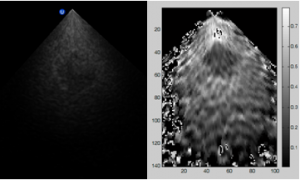
A tissue-mimicking phantom (CIRS Phantom Model 059) was fixed within the workspace of the continuum robot to enable scanning of the breast phantom by the first integrated 6 degrees of freedom snake-like system. The probe was positioned in the region of the lesion and the snake robot was used to maneuver the phased array into position to obtain images of the lesion using the Ultrasonix SONIX RP research platform. After identification of the lesion of interest was completed, several palpation motions were induced in the axial direction of the imaging plane of the phased array and a sequence of RF data frames was collected. The experimental setup is shown in the figure above which shows the US micro-array and the snake-like units. Subsequently the RF data obtained from the phantom was processed to generate strain images using a modified normalized cross-correlation method, suitable to the custom-designed phased array. Figure on the right shows a B-mode image of the lesion as well as a strain image using a pair of compressed and uncompressed RF data frames.
With the two segmented snake-like robot two more experiments were conducted. The first was very similar to the experiment detailed above except that a prostate phantom (CIRS Phantom Model 066) was used and similar results to the figure above were obtained.In this experiment, the palpation motions were generated only with the upper snake-like robot segment.Ideally, a registration could have been performed between the robot coordinate system and the ultrasonic micro-array image coordinate system to determine the direction of the imaging plane along which the palpation motions take place. However, as an alternative to this approach, the perpendicularity of the palpation was established by inspecting the up and down movement of the B-mode images on the Ultrasonix SONIX RP research platform.
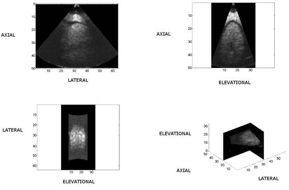
The second experiment aimed to generatea3D B-mode volumetric image of the prostate.To achieve this 3D image, the surface of the prostate phantom was swept with the ultrasonic phased array. In this sequential scan of the surface, at fixed robot angle intervals, B-mode images of the prostate were collected. Using the position information supplied from the robot unit, the images were reconstructed to form the B-mode 3D volume image of the prostate. Figure below presents the axial, lateral and elevational views and their combination on the lower right corner. The prostate contour can easily be distinguished on the upper left and upper right plots of the figure
The following videos show the image flow of the lateral, axial and elevational views of figure above.
Videos of lateral, axial, and elevational scans
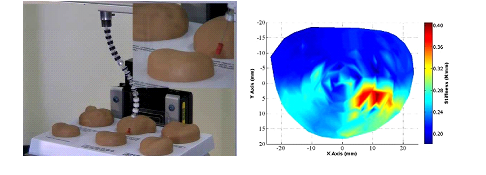
In addition to the ultrasound imaging, we have been working on integration of force sensing and stiffness imaging of tissue using snake robots. In Xu and Simaan[3][4], we have been able to demonstrate stiffness imaging of a prostate training model as shown in figure below . We believe that further integration of this palpation capability will allow surgeons to better perceive the surgical field and will lead to hybrid imaging approaches whereby ultrasound and mechanical imaging data are augmented together.
Reports and presentations
Project Personnel
-
Graduate Students
-
Tutkun Sen
-
Nishikant Deshmukh
-
-
Faculty
-
Peter Kazanzides
-
Emad Boctor
-
Russell H Taylor
-
Nabil Simaan
-
Affiliated Labs
Publications
Enabling technologies for natural orifice transluminal endoscopic surgery (NOTES) using robotically guided elasticity imaging Proceedings Article
In: SPIE Medical Imaging: Image-Guided Procedures, Robotic Interventions and Modeling, pp. 8316-8369, San Diego, CA, 2012.
Project Bibliography
[1] R. H. Taylor, J. Funda, B. Eldridge, K. Gruben, D. LaRose, S. Gomory, M. Talamini, L. R. Kavoussi, and J. Anderson, “A telerobotic assistant for laparoscopic surgery,” IEEE Engineering in Medicine and Biology Magazine, vol. 14, no. 3, pp. 279-287, 1995 .
[2] J. Funda, R. Taylor, B. Eldridge, S. Gomory, and K. Gruben, “Constrained Cartesian motion control for tele-operated surgical robots,” IEEE Transactions on Robotics and Automation, vol. 12, pp. 453-466, 1996 .
[3] K. Xu and N. Simaan, “An Investigation of the Intrinsic Force Sensing Capabilities of Continuum Robots,” IEEE Transactions on Robotics, vol. 24, pp. 576-587, June 2008 .
[4] K. Xu and N. Simaan, “Intrinsic Wrench Estimation and Its Performance Index for Multi-Segment Continuum Robots ” IEEE Transactions on Robotics, vol. 26, pp. 555-561, 2010 .